
The gyratory crushers are equipped with a hydraulic setting adjustment system, which makes it possible to regulate the gradation of the crushed material. Cone crushers . Cone crushers resemble gyratory crushers from technological standpoint, but unlike gyratory crushers, cone crushers are popular in secondary, tertiary, and quaternary crushing
 WhatsAppGet PriceGet A Quote
2. Hypothetical cross-section showing layers with parts missing----- 5 3. Hypothetical canyon that cuts through an aquifer layer: map view of representation by Canyon Cutter and Modular Model----- 7 4. Hypothetical canyon that cuts through an aquifer
WhatsAppGet PriceGet A Quote
US2440388A
A relief mechanism for a jaw crusher which includes a hydraulic fluid filled piston-cylinder arrangement mounted on the frame and connected to the rear toggle of the jaw crusher. The hydraulic fluid is connected to a pressure sensor and a relief valve. The hydraulic fluid is maintained at a predetermined pressure during normal crushing operations.
WhatsAppGet PriceGet A Quote
the piston and cylinder parts. In cylinders a pipe section is mounted, and on top of it. These parts constitute the piston part in the hydraulic cylinder. On each top section an elastomer block is fitted. (Ys) The hydraulic cylinders are single-acting cylinders (they can only press) and are supplied with hydraulic oil through bores in the
WhatsAppGet PriceGet A Quote
Fig. 1 is a side elevation view of the present crusher with a stationary jaw and a double-acting hydraulic cylinder. Fig. 2 is a top plan view of the crusher with two-sectional movable jaws. Fig. 3 is a hydraulic diagram of the crusher of Fig. 2. Fig. 4 is a kinematic diagram of a hydraulic pulser of a crank type.
WhatsAppGet PriceGet A Quote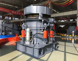
FIG. 2 is a partial cross section view of lower portion 12 of gyratory crusher 10 showing hydraulic assembly 49 which is comprised of cylindrical support 38 and piston assembly 46. Eccentric assembly 28 is shown being removed from center hub 30 by being lifted straight up in direction A, while cylindrical support 38 remains installed in its
WhatsAppGet PriceGet A Quote
Sectional View Of Hydraulic Crusher. Feb 28, 2021 Hydrocone crusher is the hydraulic support from which its name is derived and which is clearly shown in the sectional view Cone Crushers The Cone Crusher has come into almost universal use during the last few years for the final stage of crushing of the crushing cavities and feed plate arrangements Standard head cone.
WhatsAppGet PriceGet A Quote
A jaw crusher where the tension rod includes an electronically-controlled hydraulic pre-load and an automatically releasable pre-load whenever adjustments to the size of the material output are made, together with a remote visual indicator of the setting of the size of the material output.
WhatsAppGet PriceGet A Quote
A sectional view of the single-toggle type of jaw crusher is shown below. In one respect, the working principle and application of this machine are similar to all types of rock crushers, the movable jaw has its maximum movement at the top of the crushing chamber, and minimum movement at the discharge point.
WhatsAppGet PriceGet A Quote
Above figure shows sectional view of a typical gyratory crusher. Essentially, a gyratory crusher consists of a heavy cast-iron, or steel, shell/frame which includes in its lower part an actuating mechanism (eccentric and driving gears), and in its upper part a cone shaped
WhatsAppGet PriceGet A Quote
Jaw crushers are used mainly in first stage, primary crushing applications and are ideal for use in quarries and recycling demolition operations. The two main types of jaw crusher produced by Parker are both single toggle designs with the up-thrust toggle RockSizer / StoneSizer model and down-thrust toggle RockSledger model.
WhatsAppGet PriceGet A Quote
US2440388A
A relief mechanism for a jaw crusher which includes a hydraulic fluid filled piston-cylinder arrangement mounted on the frame and connected to the rear toggle of the jaw crusher. The hydraulic fluid is connected to a pressure sensor and a relief valve. The hydraulic fluid is maintained at a predetermined pressure during normal crushing operations.
WhatsAppGet PriceGet A Quote
The three types of crushers most commonly used for crushing CDW materials are the jaw crusher, the impact crusher and the gyratory crusher (Figure 4.4).A jaw crusher consists of two plates, with one oscillating back and forth against the other at a fixed angle (Figure 4.4(a)) and it is the most widely used in primary crushing stages (Behera et al., 2014).
WhatsAppGet PriceGet A Quote
FIG. 5 is a partial plan sectional view of one chain assembly taken on line 5--5 of FIG. 3. FIG. 6 is a longitudinal sectional view of the idler assembly. FIG. 7 is a perspective view of a crusher plate. FIG. 8 is a perspective view of an alternate form of a crusher plate.
WhatsAppGet PriceGet A Quote
Fig. 1 is a side elevation view of the present crusher with a stationary jaw and a double-acting hydraulic cylinder. Fig. 2 is a top plan view of the crusher with two-sectional swing jaws. Fig. 3 is a hydraulic diagram of the crusher of Fig. 2. Fig. 4 is a kinematic diagram of a hydraulic pulser of a crank type.
WhatsAppGet PriceGet A Quote
Sectional View Of Ball Mill
FIG. 2 shows a partial sectional view of a crusher that can be used in the system of FIG. 1, FIG. 3 shows a partial sectional view of another crusher. DETAILED DESCRIPTION OF THE INVENTION. Crusher 1 comprises a frame and therein a main shaft supported through a suitable bearing by a piston movable in a hydraulic cylinder.
WhatsAppGet PriceGet A Quote
Fig. 1 is a cross-sectional view of a crusher of the present invention; Fig. 2 is a hydraulic diagram of a drive means, of the present invention with a rotating distributor; Fig. 3 is a diagram of a fluidic pulser corresponding to the drive means of Fig. 1. Fig. 4 is a more detailed drawing corresponding to Fig. 1-3.
WhatsAppGet PriceGet A Quote
Sectional View Of Hydraulic Crusher. Feb 28, 2021 Hydrocone crusher is the hydraulic support from which its name is derived and which is clearly shown in the sectional view Cone Crushers The Cone Crusher has come into almost universal use during the last few years for the final stage of crushing of the crushing cavities and feed plate arrangements Standard head cone.
WhatsAppGet PriceGet A Quote
Fig. 1 is a cross-sectional view of a crusher of the present invention; Fig. 2 is a hydraulic diagram of a drive means, of the present invention with a rotating distributor; Fig. 3 is a diagram of a fluidic pulser corresponding to the drive means of Fig. 1. Fig. 4 is a more detailed drawing corresponding to Fig. 1-3.
WhatsAppGet PriceGet A Quote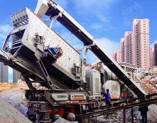
Download scientific diagram | A horizontal cross-section view through a typical cone crusher from publication: Discrete-element modelling of rock communition in a cone crusher using a bonded
WhatsAppGet PriceGet A Quote
Hydrocone crusher is the hydraulic support, from which its name is derived and which is clearly shown in the sectional view. This device makes it possible to adjust the crusher to any desired setting within its range in a matter of seconds; adjustments may be made while the crusher is running, although the feed must be shut off before operating
WhatsAppGet PriceGet A Quote
The gyratory crushers are equipped with a hydraulic setting adjustment system, which makes it possible to regulate the gradation of the crushed material. Cone crushers . Cone crushers resemble gyratory crushers from technological standpoint, but unlike gyratory crushers, cone crushers are popular in secondary, tertiary, and quaternary crushing
WhatsAppGet PriceGet A Quote
primary demolition hydraulic crusher. MC430T34. Carrier weight: 1,400 kg
FIG. 14 is a sectional left side view of the preferred rock crusher base illustrated in FIGS. 1-4 shown with a tramp iron relief system. FIG. 15 is a sectional view of the preferred tramp iron relief system illustrated in FIG. 14 taken along line B-B of FIG. 14.
WhatsAppGet PriceGet A Quote
FIG. 2 is a partial cross section view of lower portion 12 of gyratory crusher 10 showing hydraulic assembly 49 which is comprised of cylindrical support 38 and piston assembly 46. Eccentric assembly 28 is shown being removed from center hub 30 by being lifted straight up in direction A, while cylindrical support 38 remains installed in its
WhatsAppGet PriceGet A Quote
A crusher for concrete structures, having a head carried by a traveling carrier, a rotating base supported by the head concentrically therewith for rotation relative thereto, a pair of hydraulic cylinders pivotally supported at ends by the rotating base and symmetrically disposed, a pair of jaw members pivotally supported by the rotating base and symmetrically disposed, and click-stop means
WhatsAppGet PriceGet A Quote
Above figure shows sectional view of a typical gyratory crusher. Essentially, a gyratory crusher consists of a heavy cast-iron, or steel, shell/frame which includes in its lower part an actuating mechanism (eccentric and driving gears), and in its upper part a cone shaped
WhatsAppGet PriceGet A Quote
A jaw crusher where the tension rod includes an electronically-controlled hydraulic pre-load and an automatically releasable pre-load whenever adjustments to the size of the material output are made, together with a remote visual indicator of the setting of the size of the material output.
WhatsAppGet PriceGet A Quote
2. Hypothetical cross-section showing layers with parts missing----- 5 3. Hypothetical canyon that cuts through an aquifer layer: map view of representation by Canyon Cutter and Modular Model----- 7 4. Hypothetical canyon that cuts through an aquifer
WhatsAppGet PriceGet A Quote
FIG. 2 is a partial cross section view of lower portion 12 of gyratory crusher 10 showing hydraulic assembly 49 which is comprised of cylindrical support 38 and piston assembly 46. Eccentric assembly 28 is shown being removed from center hub 30 by being lifted straight up in direction A, while cylindrical support 38 remains installed in its
WhatsAppGet PriceGet A QuoteSME is a trust-worthy supplier of industrial crushing, powder grinding, mineral processing equipment and other related devices.
 No. 1688, East Gaoke Road, Pudong new district, Shanghai, China


