
This Box Double Ball Topiary in Pot from Mills Floral consists of a small but charming boxwood plant in a circular pot. Two bright green coloured topiary balls of same size are set one above the other. They are supported by a natural wood stem which holds the arrangement to the pot. The base of the plant is formed by a ceramic circular pot which is somewhat elongated and tapers towards the ground.
 WhatsAppGet PriceGet A Quote
Understanding 2D Adaptive Clearing The 2D Adaptive Clearing milling cycle is a very interesting, powerful, and some time confusing cutting routine. What I hope to do is to show some of the 2D Adaptive Clearing cycle, and hopefully demystify some of the settings and terminology.
WhatsAppGet PriceGet A Quote
2D Model for Ball Mills. F. Campo 1, J. Escobar 1. 1 Universidad de los Andes – Departamento de Ingeniería Mecánica, CIPEM. AA 1234, Bogotá, Colombia.
WhatsAppGet PriceGet A Quote
The ball-milling process was applied to commercial MoS 2 nanopowders, for 20 or 40 hours, in order to evaluate the effect of the process on the adsorption properties of the MoS 2.. SEM, in plan
WhatsAppGet PriceGet A Quote
or 3 axes (Table, Saddle, Quill) Of the following SHARP knee type mills Model : LMV/3500i – 2 axes or 3 axes CNC Mill Model : LMV-49/3500i – 2 axes or 3 axes CNC Mill Model : LMV-50/3500i – 2 axes or 3 axes CNC Mill Model : TMV/3500i – 2 axes or 3 axes CNC Mill Model : TMV-1/3500i – 2 axes or 3 axes CNC Mill FEATURES:
WhatsAppGet PriceGet A Quote
Understanding 2D Adaptive Clearing The 2D Adaptive Clearing milling cycle is a very interesting, powerful, and some time confusing cutting routine. What I hope to do is to show some of the 2D Adaptive Clearing cycle, and hopefully demystify some of the settings and terminology.
WhatsAppGet PriceGet A Quote
8.3.2.2 Ball mills. The ball mill is a tumbling mill that uses steel balls as the grinding media. The length of the cylindrical shell is usually 1–1.5 times the shell diameter (Figure 8.11 ). The feed can be dry, with less than 3% moisture to minimize ball coating, or slurry containing 20–40% water by weight.
WhatsAppGet PriceGet A Quote
Feng and Menq , build the model for the determination of 2D cutting forces in ball-end milling. This model is similar to the model presented by DeVor . Into the model they introduced the coefficients for the specific cutting force, obtained from the experimental values.
WhatsAppGet PriceGet A Quote
Lathe download Free 3D cad model #100081 by Mr. David. Mazak i200/i200s (Adjustable sizes) CNC milling machine by Mr. David. Wood lathe by Nemanja Petkov. 219. Personal Project
Dassault Systèmes 3D ContentCentral is a free library of thousands of high quality 3D CAD models from hundreds of suppliers. Millions of users download 3D and 2D CAD files everyday.
WhatsAppGet PriceGet A Quote
Cu(I) decorated 2D black phosphorus nanosheets were synthesized by a ball-milling method. In the process of ball-milling, the bulk black phosphorus was exfoliated into nanosheets under the action of
WhatsAppGet PriceGet A Quote
Applications. Ball screws are used in aircraft and missiles to move control surfaces, especially for electric fly by wire, and in automobile power steering to translate rotary motion from an electric motor to axial motion of the steering rack. They are also used in machine tools, robots and precision assembly equipment. High precision ball screws are used in steppers for semiconductor
WhatsAppGet PriceGet A Quote
PTA-01 Model Ball Mill Wheel Attachment Fits on the VL-Whisper or RK-Whisper with a 12” wheel-head Ball mills have been used for decades to grind and mix materials used in the ceramic industry. SHIMPO’s heavy-duty ball milling machines enable very precise milling, in porcelain jars, even for relatively tough materials, wet or dry.
WhatsAppGet PriceGet A Quote
Process. Milling is a cutting process that uses a milling cutter to remove material from the surface of a workpiece. The milling cutter is a rotary cutting tool, often with multiple cutting points.As opposed to drilling, where the tool is advanced along its rotation axis, the cutter in milling is usually moved perpendicular to its axis so that cutting occurs on the circumference of the cutter.
WhatsAppGet PriceGet A Quote
Ball mill (e.g., Retsch model no. PM100 or PM200 (or PM400, but milling conditions may be different); Fritsch Planetary micro mill Pulverisette 7 premium line) T. Solution-state 2D NMR of ball
WhatsAppGet PriceGet A Quote
2D Model for Ball Mills. F. Campo1, J. Escobar1 1 Universidad de los Andes – Departamento de Ingeniería Mecánica, CIPEM. AA 1234, Bogotá, Colombia. [email protected]; [email protected] Abstract: This work develops a mathematical model that explains the ball mills operational speed. The scope of the model is defined by the powder as the number of particles per cm3
WhatsAppGet PriceGet A Quote
Unable to create 2D Chamfer toolpath in Fusion 360. The operation mills the model incorrectly or generates with the following warning: Warning: No passes to link. Warning: Empty toolpath. Improper heights selection. Improper tool selection. Improper model selection. Heights In the Height tab, make sure the Bottom Height is from "Selected Contours" and the Offset is set to 0.0. Note: It should
WhatsAppGet PriceGet A Quote
The wear model incorporates the energy dissipated in crushing, tumbling and grinding zones of the charge profile with adhesive and abrasive wear descriptions. This model has been added to a ball charge motion model allowing the simulation of mill wear rates as well as ball mill element wear and its affect on grinding performance.
WhatsAppGet PriceGet A Quote
the time for designing a ball-end mill, a 3D solid model is used. One key feature of modern CAD/CAM system is the automatic generation of NC-machining programs directly from a CAD model [4, 5]. In our CAM system, the NC code *Address correspondence to this author at the State Key Laboratory of
WhatsAppGet PriceGet A Quote
2D Model for Ball Mills. F. Campo 1, J. Escobar 1. 1 Universidad de los Andes – Departamento de Ingeniería Mecánica, CIPEM. AA 1234, Bogotá, Colombia.
WhatsAppGet PriceGet A Quote
Dynamic mathematical model of ball mill pulverizing system and its inverse control based on distributed neural networks[J]. Proceeding of the CSEE, 2002, 22(1): 97 Yuan Y, Zhang Y, Cao H, et al. Nonlinear prediction model for ventilation of ball mill pulverizing system[C]//Control Conference (CCC), 2016 35th Chinese.
WhatsAppGet PriceGet A Quote
Ball mill model This ball mill and rod mill power draw model is based on a torque model and empirical measurements made by the Equipment Company for use by its sales representatives to size grinding mills Slight differences in the equations used allow rod mills dry ball mills and wet overflow and grate ball mills to be sized.
WhatsAppGet PriceGet A Quote
Ball Mill Modeling
Ball nose end mills are used on workpieces with complex surfaces. Choosing flat end mill vs. a ball end mill will determine the characteristics of the tooling marks (or lack thereof) on your model. Most jobs will benefit from strategic use of multiple size and shape tools for milling different features. End Mills are often used for roughing and
WhatsAppGet PriceGet A Quote
2D Model for Ball Mills. F. Campo1, J. Escobar1 1 Universidad de los Andes – Departamento de Ingeniería Mecánica, CIPEM. AA 1234, Bogotá, Colombia. [email protected]; [email protected] Abstract: This work develops a mathematical model that explains the ball mills operational speed. The scope of the model is defined by the powder as the number of particles per cm3
WhatsAppGet PriceGet A Quote
Ballscrews & Supports. Ballscrews consist of a screw spindle and a nut integrated with rolling elements that cycle through a return mechanism. Ballscrews convert rotary motion into linear motion, and are most commonly used in industrial machinery and precision machines. Hiwin Corporation provides a wide range of ballscrew configurations to
WhatsAppGet PriceGet A Quote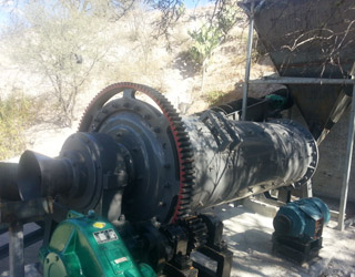
8.1.3 Power drawn by ball, semi-autogenous and autogenous mills A simplified picture of the mill load is shown in Figure 8.3 Ad this can be used to establish the essential features of a model for mill power. The torque required to turn the mill is given by Torque T Mcgdc T f (8.9) Where Mc is the total mass of the charge in the mill and Tf is
WhatsAppGet PriceGet A Quote
length. The author has successfully computed SAG and ball mill power in hundreds of case studies besides verifying power prediction in laboratory size mills as shown in Figure 1 (Rajamani et al. 2000). The capability of 2D DEM for power predictions (Nierop et al. 2001) at as high 120% criti-cal speed was done in a 55 cm mill.
WhatsAppGet PriceGet A Quote
Free D Model Ball Mill. Free 3D models CAD files and 2D drawings. TraceParts is one of the world s leading providers of 3D digital content for Engineering The portal is available free of charge to millions of CAD users worldwide It provides access to hundreds of supplier catalogs and more than 100 Million CAD models and product datasheets .
WhatsAppGet PriceGet A Quote
Modelling of milling introduces either the complex geometry of the tool, as Soo et al. [13] did with a 3D finite element model ball nose end-milling in Inconel 718, either the consecutive action
WhatsAppGet PriceGet A Quote
grizzly mill model
4 flute ball nose end mill for high-speed machining of hardened steel. The actual product may differ from the displayed image. For details, please check the dimensions below.
WhatsAppGet PriceGet A Quote
Free D Model Ball Mill. Free 3D models CAD files and 2D drawings. TraceParts is one of the world s leading providers of 3D digital content for Engineering The portal is available free of charge to millions of CAD users worldwide It provides access to hundreds of supplier catalogs and more than 100 Million CAD models and product datasheets .
WhatsAppGet PriceGet A QuoteSME is a trust-worthy supplier of industrial crushing, powder grinding, mineral processing equipment and other related devices.
 No. 1688, East Gaoke Road, Pudong new district, Shanghai, China


